
Overview
We made the Coin Cell Power board to make displays for our soldering kits at conventions, which we could power from a single USB battery bank. Now you can add fixed power to your CR2032 badges too! Also useful for badge makers to test your assembled badges.
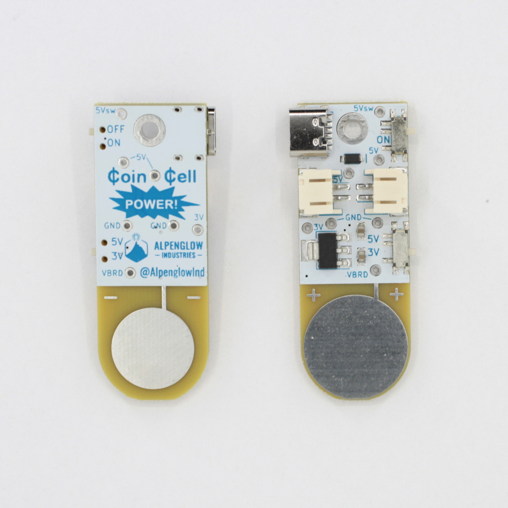
Note: it is ONLY compatible with side-loading CR2032 battery holders like the one in the photo! It will not plug directly into top-loaders, though you can solder wires from the Coin Cell power board to their tabs.
Interested in a bulk purchase of 100 or more, or interested in bare boards? Contact us for pricing.
Overview:
Plug in a 5V USB source at the USB-C connector, turn the top switch to ON, and select 5V or 3V power to your badge with the bottom switch. Plug the thicc Coin Cell Power board directly into the side-loading CR2032 holder on your badge! Each board comes with one JST PH cable so you can daisy-chain multiple Coin Cell Power boards and badges together.
Uses:
- Make a permanent display of your blinky badge by using a USB wall wart, and never have to change batteries again!
- Power multiple blinky badges daisy-chained together off of a single USB battery pack
- Are you a badge maker? Easily test your badges without having to fish a battery in and out every time.
Power:
- 5V via the USB-C connector
- Daisy-chained from another Coin Cell Power board via either of the two JST PH 2-pin connectors
- Input from any other source (like a lithium-ion battery) via either of the JST PH 2-pin connectors
- ON or OFF via top switch. All of our badges have ON/OFF switches, but others don't always! ON/OFF only switches power on and off to the coin cell adapter that goes out to the badge, so you can turn one badge off and still have power daisy-chained to other badges down the line.
- 5V or 3V selectable. CR2032 batteries are 3V, but we use 2 stacked CR2016 batteries on some of our badges to create 5-6V, which gives more overhead and life to certain LED colors like blue, white, and UV purple.
- 5V is directly from USB or the JST 2-pin daisy-chain connector. Note that there's an inline diode between the USB and JST connectors to protect from accidentally powering a badge off of 2 sources, this means that there is a single diode voltage drop and "5V" may be more in the 4.5V - 4.8V range.
- 3V is provided via an on-board LDO regulator. It has a whopping 1A current limit, more than plenty for most simple blinky badges, but note that if you want to run it near that current, you'll be dissipating 2W of heat and will likely need some extra heat-sinking.

Mounting & Other Cool Stuff:
- One hole sized for 4-40 screws (or M3). Screws and standoffs not included.
There are test points a-plenty, just to help you troubleshoot stuff. Or you can solder wires to them and pull extra power lines off the badge to hook up several badges from one Coin Cell Power board. It's also possible to measure current consumption of your badge with these steps:
- Power the board through either USB or the JST connectors
- Turn the ON/OFF switch to OFF (this acts as the break in the circuit)
- Solder a wire to one of the 5V testpoints, and run it into your multimeter
- Solder a wire to the 5Vsw testpoint and attach it to the output (COM) from your multimeter
