
Overview
Breadboard Compatible ISP adapter, with a minimal footprint that doesn't obstruct much of the breadboard, and a switch for connecting or disconnecting power from your programmer to your breadboard. This comes as a kit and requires soldering.
It is a breadboard compatible ISP header that plugs into the power rail, and takes up minimal space, obstructing as few connection points as possible. It has an ON/OFF switch for either connecting power between your breadboard and programmer, or isolating power. An LED indicates whether power is connected (ON) or not (OFF).
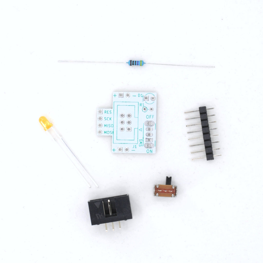
Solder Top components
We like soldering the switch first, then the LED and resistor, then the 6-pin ISP connector.


Solder Bottom Headers
After that, you can use a breadboard as a jig by placing the remaining 4 headers that are on the bottom into the breadboard to hold them in place, drop the PCB over top of them, and then solder them in.

10-pin to 6-pin Adapter Orientation
If you are using a 10-pin to 6-pin adapter the side that says MISO, SCK, RST should be facing toward the notch in the pin connector. We've marked ours below with a silver sharpie so we know that way always lines up with the notch.

How it Works!
We love little handy boards and made this one to be a super compact little breadboard-compatible ISP header. With Power! It keys into a breadboard's power rails, with a switch to either connect or disconnect power from the programmer to the breadboard, and an LED for indication (on = power, off = no power). It then passes the 4 signal lines (RESET, SCK, MISO, MOSI) to the breadboard, covering the minimum 4 holes. The ISP connector is situated over the power rails, between 2 power rail headers for extra stability. The switch and LED hang off the side of your breadboard, so they're out of the way. See, we thought of everything!
ISP stands for In-Circuit Serial Programmer and is a programming format used for AVR microprocessors, like the ATMEGA328P in the Arduino Uno. With a programmer like the USBasp, you can directly program AVRs and burn bootloaders.


Elsewhere on the Web
Downloads
How to download our BOM from GitHub:
1. Click the BOM button above
2. Right click over the raw data
3. Select save as and save the CSV file
Have any questions? Contact us!