
The SMT Garden Guide
Overview
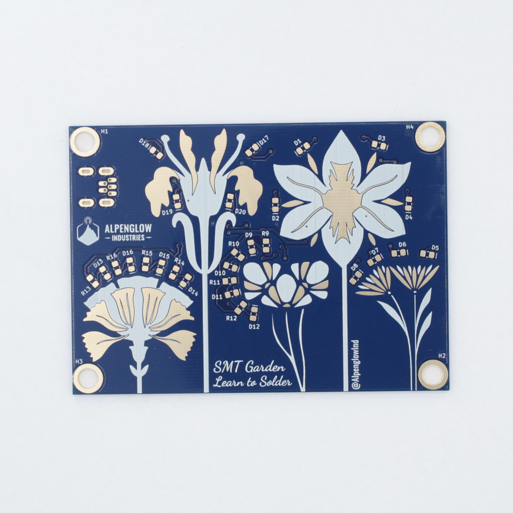
Practice your SMT Soldering skills with the SMT Garden! This is our "official" beginning SMT soldering kit, with a practice area for several sizes of components, and a blinking circuit made with all 0805 components.
With our official learn to SMT solder kit you will be able to practice soldering different sized components ranging from 1206 all the way down to 0402. We also included mini-melf and SOD-323 diodes. There are "practice stalks" that have some grounded pads to give you some experience soldering to pads with heat sinking. The 0805 components are part of the circuit along with two dual 555 timers and an inverter which create 5 different blinking rates. We've included a bunch of different colored LEDs so you can choose whichever colors you want for your flowers!
What's in the kit?
- 10 - Practice capacitors 1206, 0.1 uF
- 10 - Practice capacitors 0603, 100nF
- 10 - Practice capacitors 0402, 0.1 uF
- 10 - Practice resistors, 10 ohms, 1206
- 10 - Practice resistors, 1.00k, 0603
- 10 - Practice resistors, 10.0k, 0402
- 10 - Practice diodes, SOD-80 mini-melf
- 16 - Reverse-polarity protection diodes and practice diodes, SOD-323
- 5 - Red LEDs
- 5 - Orange LEDs
- 5 - Yellow LEDs
- 5 - Green LEDs
- 5 - Blue LEDs
- 25 - 1.00k ohm resistors for red, org, yel, grn, blu LEDs, 0805
- 6 - 10M ohm resistors, 0805
- 2 - 22M ohm resistors, 0805
- 3 - 4.7M ohm resistors, 0805
- 5 - 0.1 uF / 100 nF ceramic chip capacitor, 0805
- 8 - 0.01 uF / 10 nF ceramic chip capacitor, 0805
- 2 - Dual 555 timers, SO-14
- 1 - Inverter, SO-14
- 1 - USB Mini B thru
- 1 - Magnetic standoffs, set of 4 with screws
- 1 - PCB
Start with the 1206 capacitor and resistor practice stalks
Gather your supplies. You'll need:
- a soldering iron (60W min) set to 700-750F (370-400C)
- a fine but not sharply pointy tip (0.8mm is good and we prefer bent tips)
- a flux pen (rosin RMA or water-soluble, most no-clean is not active enough)
- small diameter solder (0.4mm or below is best)
- tweezers (we like curved tip ones, but straight work too. They need to be very pointy to pick up small components.)
Flux is very important for surface mount soldering. You'll be using smaller diameter solder (we like 0.4mm), and it will contain less flux than typical larger-diameter solder. So the first step before you start to solder is: always coat the pads with flux.


How to Use Flux:


How to Remove Components from Tape:
Do this over a desk so that your components drop straight to your work surface. A soldering mat is very handy, especially the ones with small compartments molded in. Either use a fingernail, or grab your tweezers and insert under the clear tape at the end. Then slowly pull back. Your components might jump out at this point, that's OK. Turn the tape over and tap to release all components.
Note: When soldering the actual circuit, only release the number of parts needed! This helps you detect mistakes - if you find you have an extra or are one short, you may have soldered a component in the wrong place!


How to Hold Tweezers:


How to SMT Solder
Technique 1 - "Tacking":
Step 1: Gently hold the component with tweezers and get a small ball of solder on the tip of your iron. Touch it to the fluxed pad (important that the pad already have flux on it!). This will create a not-so-great solder joint, but it'll suffice to hold the component in place.
Step 2: Now solder the other side normally, by holding the solder in your non-dominant hand, and touching it to the iron and the pad simultaneously. This will create a nicely flowed solder joint.
Step 3: Add flux to the first not-so-great solder joint with the flux pen. Reflow the joint with the iron. Now it should be a nice smooth solder joint!

Technique 2 - "Blobbing":
Step 1: Coat one already-fluxed pad in a blob of solder. (Use one of the non-grounded pads).
Step 2: While reflowing the solder with one hand, hold the component with tweezers in the other hand and scoot it onto the pad with solder. Make sure the component is flat, and that there's enough space on the non-soldered pad for the iron tip!
Step 3: Solder the other pad normally, by holding the solder in one hand, and touching it to the iron and the pad simultaneously. This will create a nicely flowed solder joint.
Step 4: Add flux and reflow the first solder joint if needed.

Soldering GND Pads:

How to Identify a Good Joint:
A good joint should have just enough solder to create a nice concave "fillet" between the pad and the metallized side of the component. If yours is convex and blobbly, it's OK as long as it's not in danger of touching (or "bridging" to) a nearby component.
People make a lot of fuss about leaded solder making nicer joints. While they are shinier, lead-free solder is much more environmentally friendly, so you might as well get used to it from the start. All these examples use lead-free solder, and it's not hard to tell a good joint from a bad one. Note that it's normal for good joints to appear very shiny when the solder is still molten, and then "dull over" as it hardens.

How to Identify a Bad Joint:

SMT Soldering Tips and Tricks:
- If the board is moving around too much on you, just tape it down to the table. Eventually, you'll develop enough dexterity to hold the board down with one finger on your non-dominant hand, while holding the component with the tweezers.
- If you're finding it hard to get the correct angle, don't move your hands to an awkward position, just move or rotate the circuit board!
- If your hands are shaking - do not fear, mine do too, this is normal! You can steady your hands by touching the heels of your palms to the surface of the table you're working on. This stabilizes your entire hand and allows your fingertips to do the more dexterous work of finely positioning the component and soldering iron tip.
- If you're having trouble with the solder flowing, check a few things. You can try increasing the temperature, but if you're still having trouble at 750F, it's probably not the temperature. 60W or higher irons are recommended for being able to heat up GND pads. The very tip of the iron tip is the coldest part, so if your iron tip is extremely sharp, it might not be getting hot enough. Try a wider one. Check your solder - formulations with silver (SAC - Sn/Ag/Cu) flow much better than Sn-Cu only formulations. Your tip may be oxidized - try cleaning it (when cool) with a bit of brass wool. You can use tip tinner for stubborn tips, but note it will decrease the life of the tip. Get in the habit of always putting away your tip "dirty" - meaning tinned/coated with solder. Check the type of flux, use rosin RMA or water-soluble, and add more.
Solder the practice diodes and circuit diodes

Note: Diodes are directional! be sure to match the line on the footprint to the marking on the component. The line should always denote the cathode.
Use the same techniques described above to solder the diodes, and all subsequent components. We've provided two styles of diodes - the orange glass ones are mini-melf packages, and the black ones with legs are SOD-323 packages. Other styles with flat or J leads exist too.
After soldering the SOD-323 diodes to the practice stalk, you can solder the ones that are part of the circuit (D21-D26 shown above).


Solder 0603 capacitor and resistor practice stalks
Now that you've aced 1206's and diodes, let's jump to smaller 0603 footprints. These you will likely want magnification for. Even if you can see them well enough with your bare eyes to solder, you'll still want magnification to fully inspect your joints! Several different tools can be used: a magnifying glass or magnifying ring light, magnifying head-mounted glasses, or a stereo microscope. It is more difficult to solder well under a USB camera microscope or a monocular microscope because you lose all depth perception.
Soldering these is the same process as the above, they're just smaller components. You might fling them across the room with your tweezers more, practice that just-enough pressure holding. If you don't have magnification, you can always save these for later and jump to soldering the chips (aka ICs) and the 0805s in the actual circuit. The 1206s and 0805s are good enough practice to start!

If you're feeling confident, move on to the 0402 practice stalks

Solder the Chips - Dual 555 timers and Inverter
Dual 555 timers (556 chips) (U1, U3) Inverter (U2) |

These components are directional!

Here are some examples of good and bad soldering on an inverter chip |

Solder 0805 capacitors
0.1uF capacitors (C1, C6, C7, C10) |


Solder 0805 resistors
10M resistors (R21, R25 - R28) |


Solder LED resistors to the back of the board
Resistor numbers match up with LED numbers, so R17 is the resistor that feeds D17. We've made it easy for you and are using the same value of resistor for all LEDs, so you don't have to worry about mixing them up and your LEDs being much different in brightness. They're all pretty bright! After soldering, all the LEDs in each flower will blink simultaneously, but each flower will blink at a different rate! You can make each flower a different color, or each flower multiple colors. Get creative!
Note that half the resistors for the LEDs are on the back of the board, and half are on the front (you'll solder those soon).

Solder USB Connector


Add magnetic standoffs to each corner

Solder LEDs and remaining resistors on the front of the board

Resistors 1k ohm (R9-R16)
LEDs (D1-D20)


Plug into power or solder on battery holder


You can attach the battery holder to the back of the board with double-sided tape or adhesive dots. Or not - you might want to show off all those excellent joints!
The battery holder has an on/off switch, to light up your board, switch it to on!
Enjoy the colorful flashing fruits ..er.. flowers of your labor!

Powering your board
You can either power your board with the battery holder and CR2032 batteries included with your kit or you can power your board through the USB connector with any USB mini B cable.


Use the magentic stand offs to decorate your fridge!

Backstory
Elsewhere on the Web
Downloads
1. Click the BOM button above
2. Right click over the raw data
3. Select save as and save the CSV file