


Details
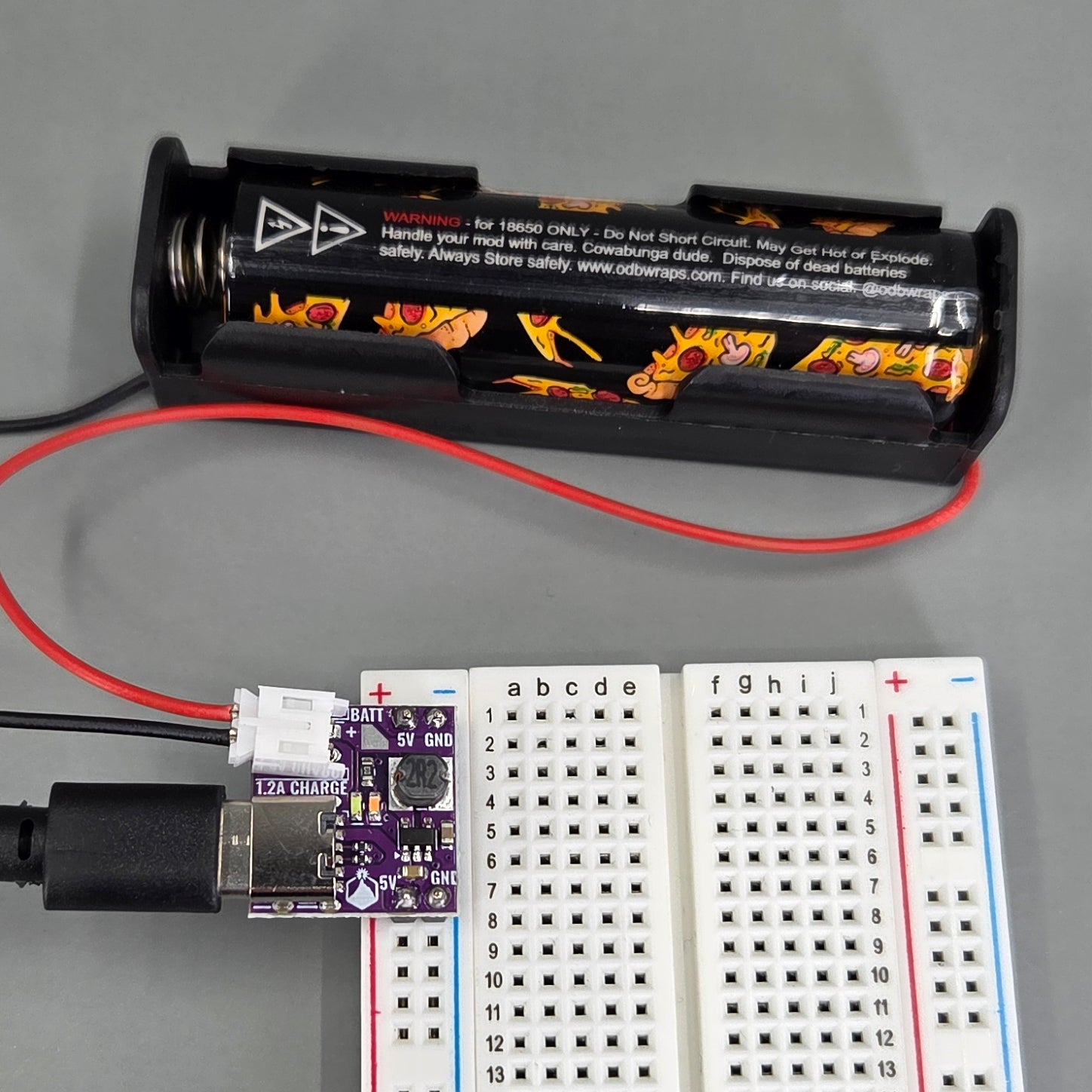
Make your own power bank out of any (1000 mAh or over) lithium battery!
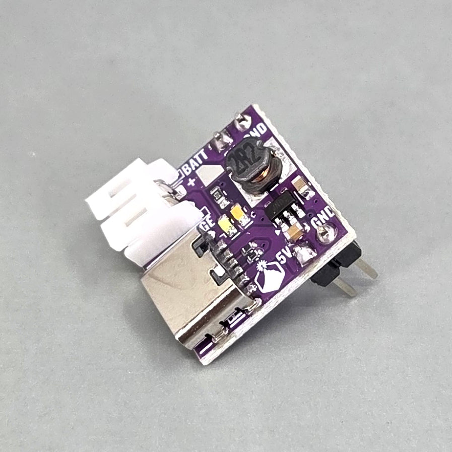
Are you a fan of bi-directional USB-C? Hey, so are we! This awesome little board goes both ways - the USB-C connector is both an input to charge a lithium battery at 1.0-1.2A and an output that provides a boosted 5V from the battery at 1.2A! If you're like "there's no way a SOT-23-5 chip can do all that and have two LED outputs, there just aren't enough pins" yeah that's what we initially thought too until we kept thinking, drew out a diagram, and realized, holy shit yeah you can just do it in 5 pins if you have a fixed charge current. Also, if you have a low current application and are struggling to find 18650 power packs that don't need a minimum output current to function, this little puppy will happily provide uA (and maybe nA?) of current for processors in sleep mode.
What else is awesome about this board?
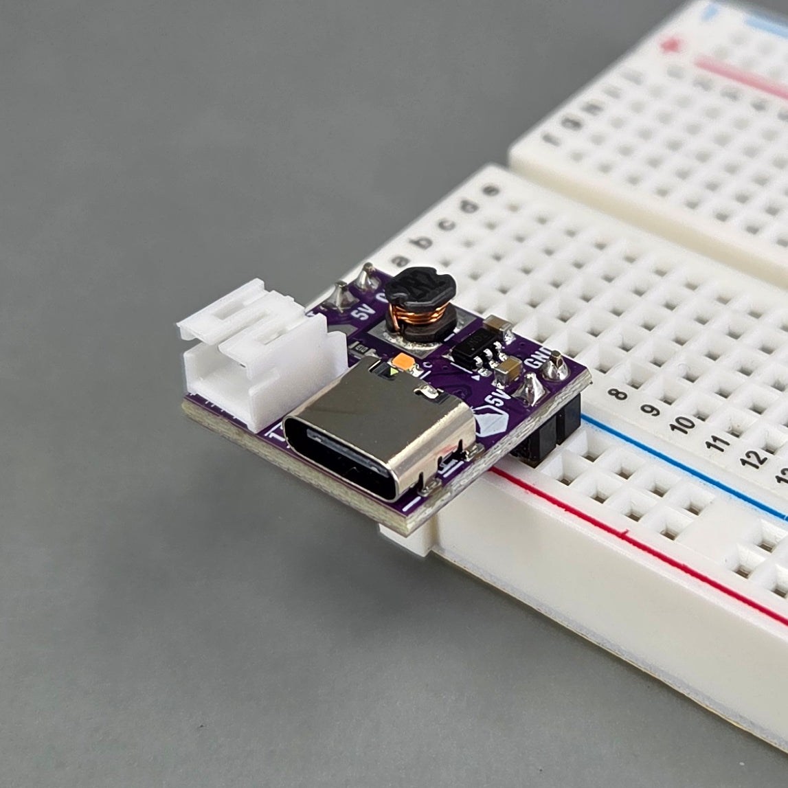
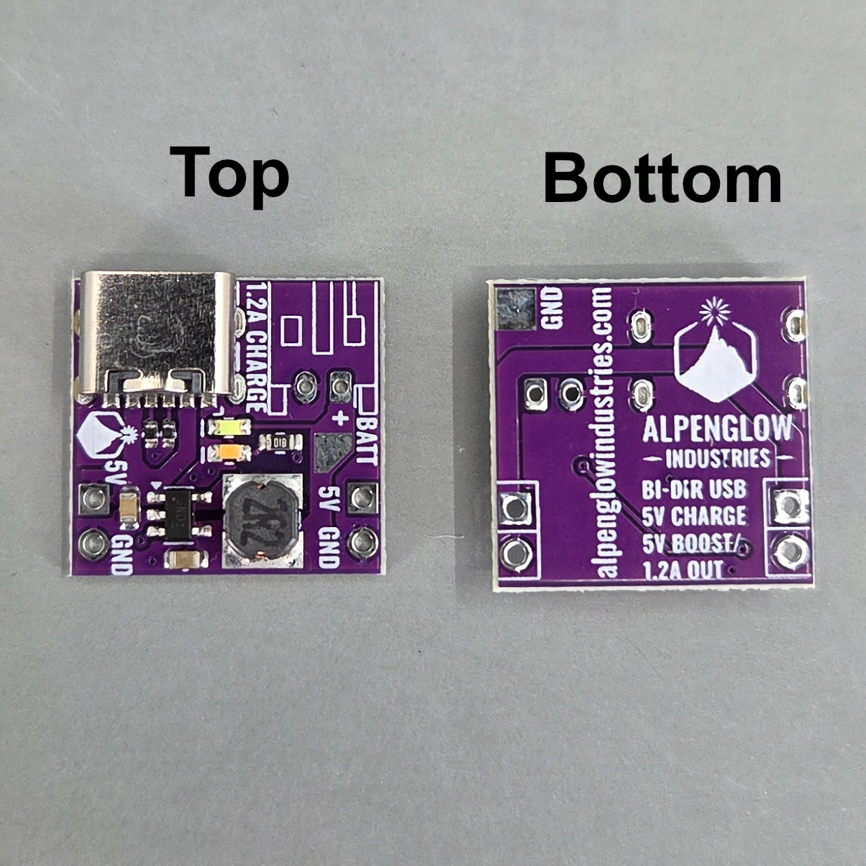
- It's breadboard-compatible - the 5V input/output plugs right into a power rail
- There are 2 headers for the power rail spaced 0.6" apart - plug both in and have a super stable board that overhangs your breadboard or plug only the bottom one into the corner of your breadboard for minimal hole occlusion.
- Convenient JST-PH 2-pin connector for the battery
- Works with any USB-C or USB-A power supply (onboard CC resistors)
- Very tiny and cute (17.3 x 18.0mm)
Specs:
- Fixed 1.2A charge current - this is important, only use larger lithium batteries that are OK to charge at this current, do not plug a tiny LiPo into this board.
- Trickle charge mode - charges at 200 mA for batteries under 2.8V, then switches to full charge current
- Low current discharge - this will happily output small uA level currents and keep a processor in sleep mode going, unlike other battery bank chips that require a minimum discharge current to function.
- 5V boosted output - regulation is good up to 1.0A output, output voltage drops between 1.0A and 1.2A output current
- 5V output short circuit protection - stops discharge, hiccups every 2 seconds until short is removed
- 5V output overcurrent protection - stops discharge ~2.5A
- Battery overdischarge/undervoltage protection - discharge stops when battery drops below 2.7V
- Battery overcharge/overvoltage protection - charger goes into constant voltage mode just below 4.2V and stops charging when current dips below 100 mA.
- Thermal protection: charge stops at 85C, full shutdown at 150C
- Soldering required: the 2-pin JST-PH connector and 5V/GND headers. Both are optional, you can directly wire a battery and 5V load to these holes. A + battery pad is also provided on the top of the board and a - (GND) pad on the bottom of the board.
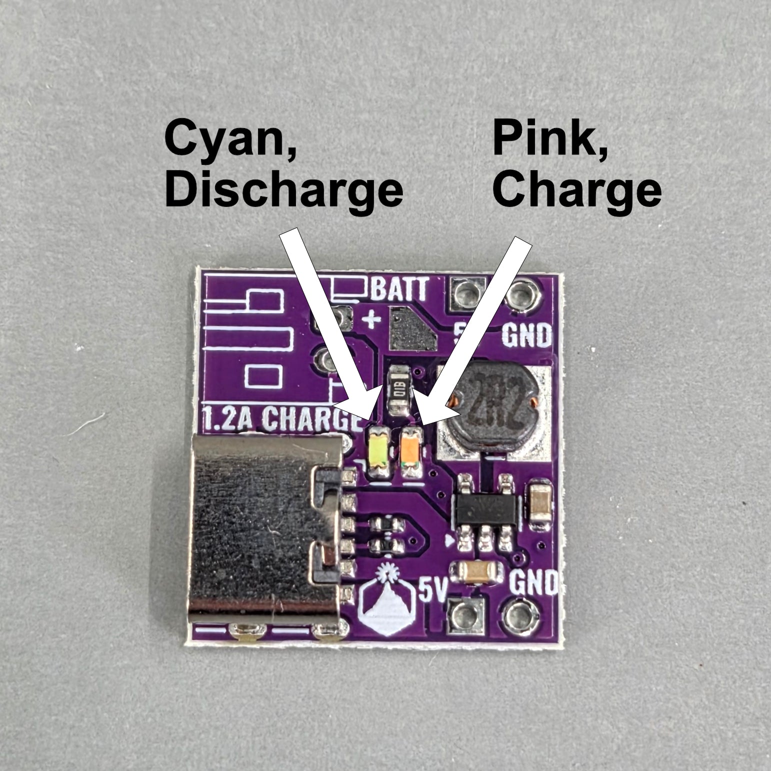
LED Indication:
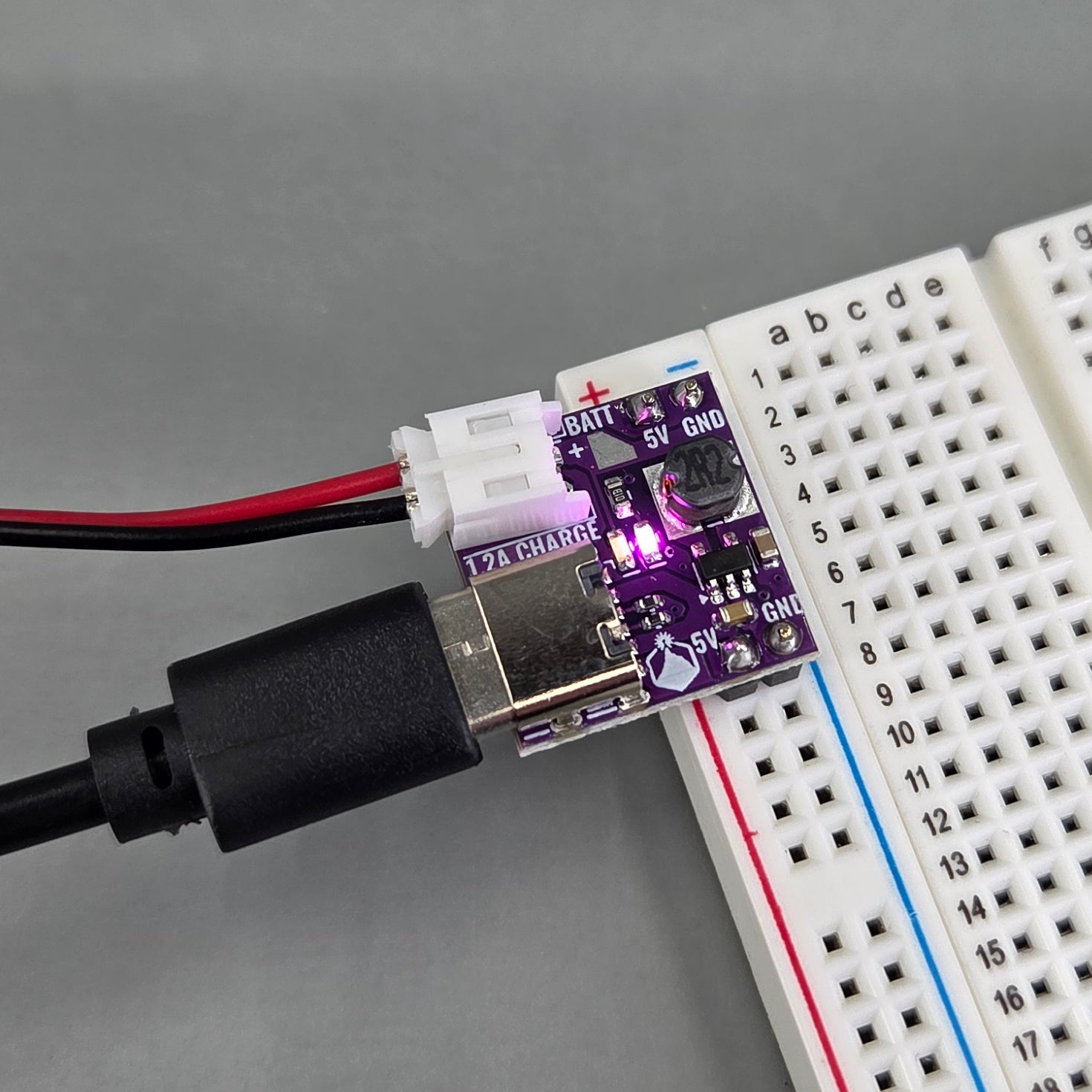
- Pink blinking: charging or no battery, charging mode (I know, bummer that it doesn't distinguish)
- Pink solid: fully charged, charging mode (USB is still providing 5V for charging)
- Cyan solid: discharging, boost mode (a load is plugged into USB)
- No lights: 0-15mA load current, discharge mode (a small load or no load is plugged into USB)