


Details
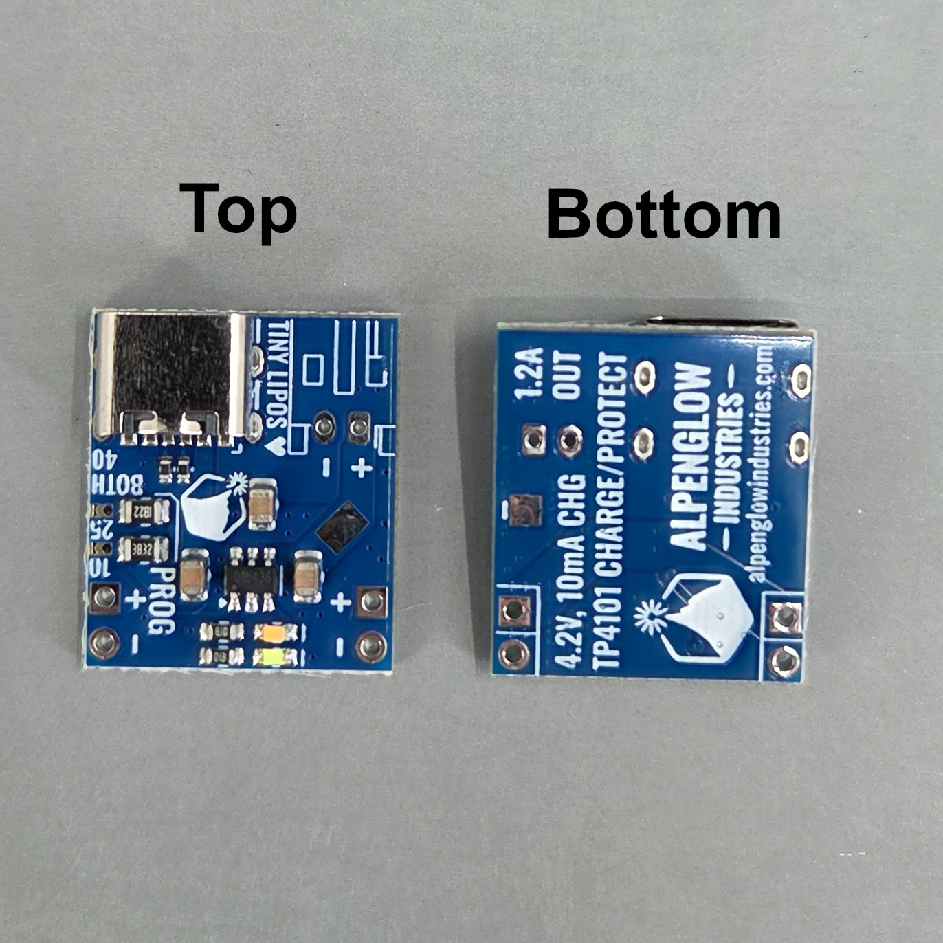
Got some really tiny 30 mAh LiPos and are all of your chargers 100 mA or more? Treat those little lithium polymers with kid gloves with our Tiny LiPo Charger Kit! This is a set of 3 boards set to 10mA, 25mA, and 40mA nominal charge currents (actual charge currents may be 2-10mA higher due to resistor tolerances). Note that this board has undergone a revision, new boards are blue, old boards are green and were all set to 10 mA.
What's even cooler about this chip is that it has built-in undervoltage/overdischarge protection, so it can even be used in a project with unprotected lil' LiPos or supercapacitors! The battery discharge output is fully isolated from the battery input, so this chip has some cool protections that most chargers don't, like output short circuit protection and battery reverse polarity protection.
Nice Features:
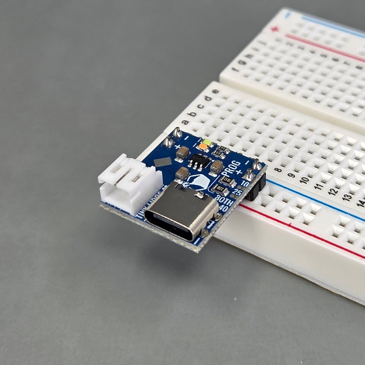
- Breadboard-compatible, battery output plugs right into a power rail
- There are 2 headers for the power rail spaced 0.6" apart - plug both in and have a super stable board that overhangs your breadboard or plug only the bottom one into the corner of your breadboard for minimal hole occlusion.
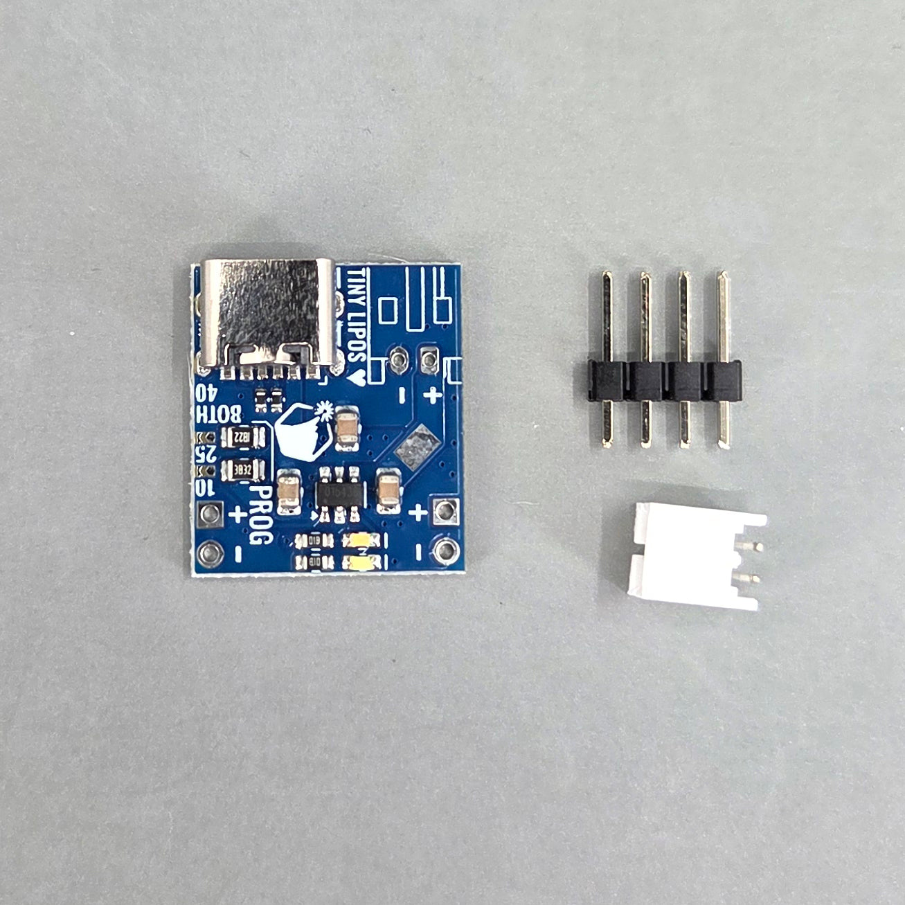
- Convenient JST-PH 2-pin connector for the battery
- Works with any USB-C or USB-A power supply (onboard CC resistors)
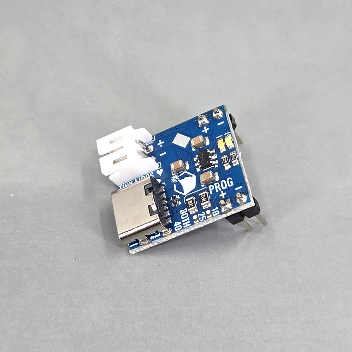
- Very tiny and cute (18 x 20.5mm)
Specs:
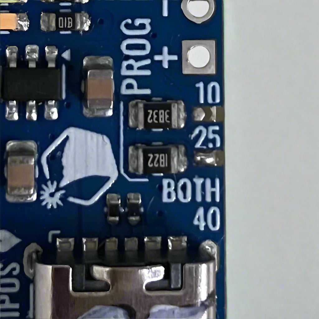
- 10 mA, 25mA, and 40mA charge current: this can be changed by swapping resistors if you are very comfortable with surface mount soldering. This board was initially set up for solder-blob selection, but proved more difficult to solder than intended. We've done the hard part for you and used 0 ohm jumpers to set each board at a fixed charge currrent.
- 1.2A discharge current: max continuous at any battery voltage level, or limited by your battery capacity for tiny LiPos
- Battery reverse polarity protection: if the battery is hooked up backwards, nothing bad happens
- Output reverse polarity protection: the output is disconnected from the battery, no current is drawn, hiccups every 8 seconds
- Output overcurrent/short circuit protection: same behavior as above when output current reaches 1.7A.
- Undervoltage protection: output is disabled when the battery voltage drops to under 2.8V.
-
Overcharge protection: goes into constant-voltage charge mode just under 4.2V and terminates charging at 1 mA (or 10% charge current setpoint)
- Trickle charge mode: for batteries discharged to low voltage, it automatically trickle charges at 2 mA (or 20% charge current setpoint) until the output reaches 3.2V, then goes to the full charge current
- Thermal protection: chip disabled at 145C
-
Soldering required: The 2-pin JST-PH connector and BATT+/- output headers provided are optional, you can directly solder a battery wire and/or load to these holes instead. A + battery input pad is also provided on the top of the board and a - (GND) pad is on the bottom of the board.
LED Indication:
- Pink Solid: charging
- Cyan Solid (Pink may be dim): fully charged
- Cyan Solid, Pink Flashing: USB power present, no battery
- No LEDs: no USB power
Resistor Charge Current Setting:
If you want to set it to a different charge current, these chips can supply anywhere from 3mA to 1000 mA depending on the resistor populated. These two equations were given in the datasheet, which aren't very accurate especially at low charge currents. R is in kohms and IBAT is in mA.

We've found their data and our own fit to an exponential decay curve very well, so at the risk of slightly more complicated math, we've found this equation to be an almost perfect match:
